RC circuits
Analysis of circuits containing resistors and capacitors
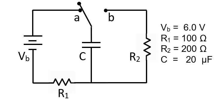
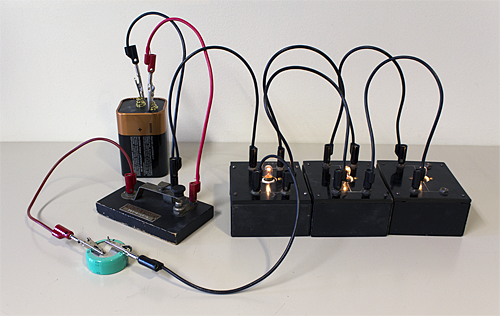
The circuit diagram above depicts an RC circuit. An RC circuit contains resistors and capacitors, at least one of each.
This simple circuit illustrates the fundamental behavior of an RC circuit.
When the switch is closed in the "a" position, electrons flow from the battery onto the negative capacitor plate,
and an equal deficit of electrons is simultaneously created on the positive capacitor plate as electrons flow away from it.
Charges flow until the potential of the capacitor equals that of the battery.
The capacitor is then fully charged for this circuit.
When the switch is closed in the "b" position, the battery is no longer in the circuit, and the electrons flow from the
negative plate toward the positive plate until the charge is balanced, and the capacitor is completely uncharged.
This charging and discharging takes time. We can analyze the circuit to figure out how much time the charging and discharging takes.
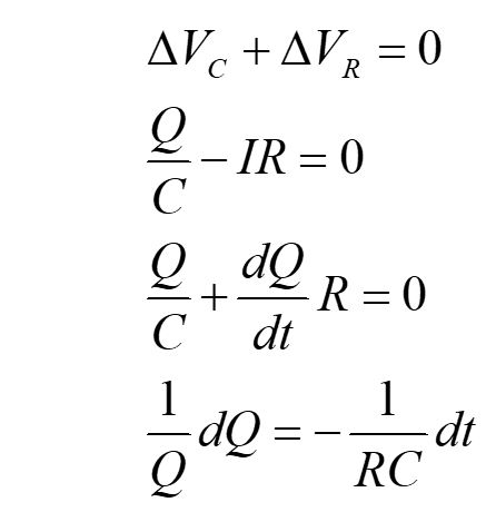
We start by using the loop rule for the discharging circuit and substituting in terms for the potential drops
across the capacitor and resistor. Since charge is decreasing, the definition for current as dQ/dt is negative.
We then use separation of variables to write the equation in a form we can easily solve.
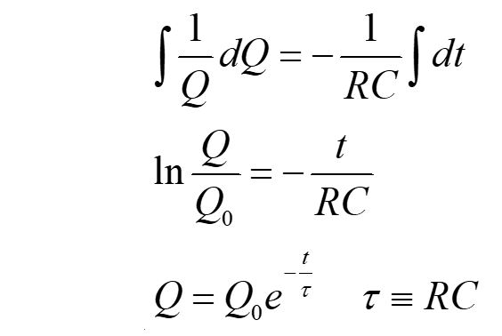
Integrating both sides, we solve the differential equation and then rewrite in terms of the charge Q at time t
and the initial charge Q0. The time constant τ is defined as RC.
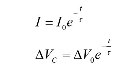
We can take the derivative of charge with respect to time to write this equation in terms of the current
and use simple substitution to write the potential difference equation for a discharging capacitor.
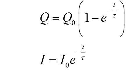
We can use a similar analysis to find equations for the charge on a capacitor in a charging circuit,
and for the current through the resistor. For this derivation, we need to include the EMF in our basic equation.
Both charging and discharging circuits have have currents that decay exponentially over time.
This makes sense, since right after the switch is closed, the current is flowing the fastest.
In the charging circuit, the current slows as the charges populate the capacitor plate. It gets harder and harder to
put more charge onto the plate.
For the discharging circuit, the current slows over time because less charge separation
means the forces pushing the charges apart decrease as the charge becomes balanced (neutral).
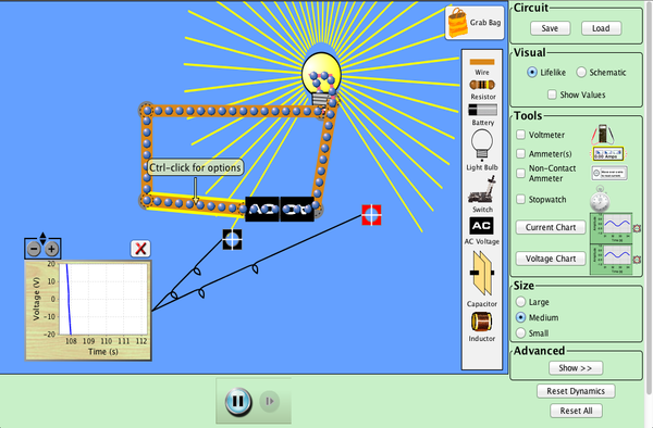
Click to Run
Try using this PHeT demo to investigate a charging and discharging RC circuit.
| Click to Run |
