PH 213 topics
Resistors in series and parallel
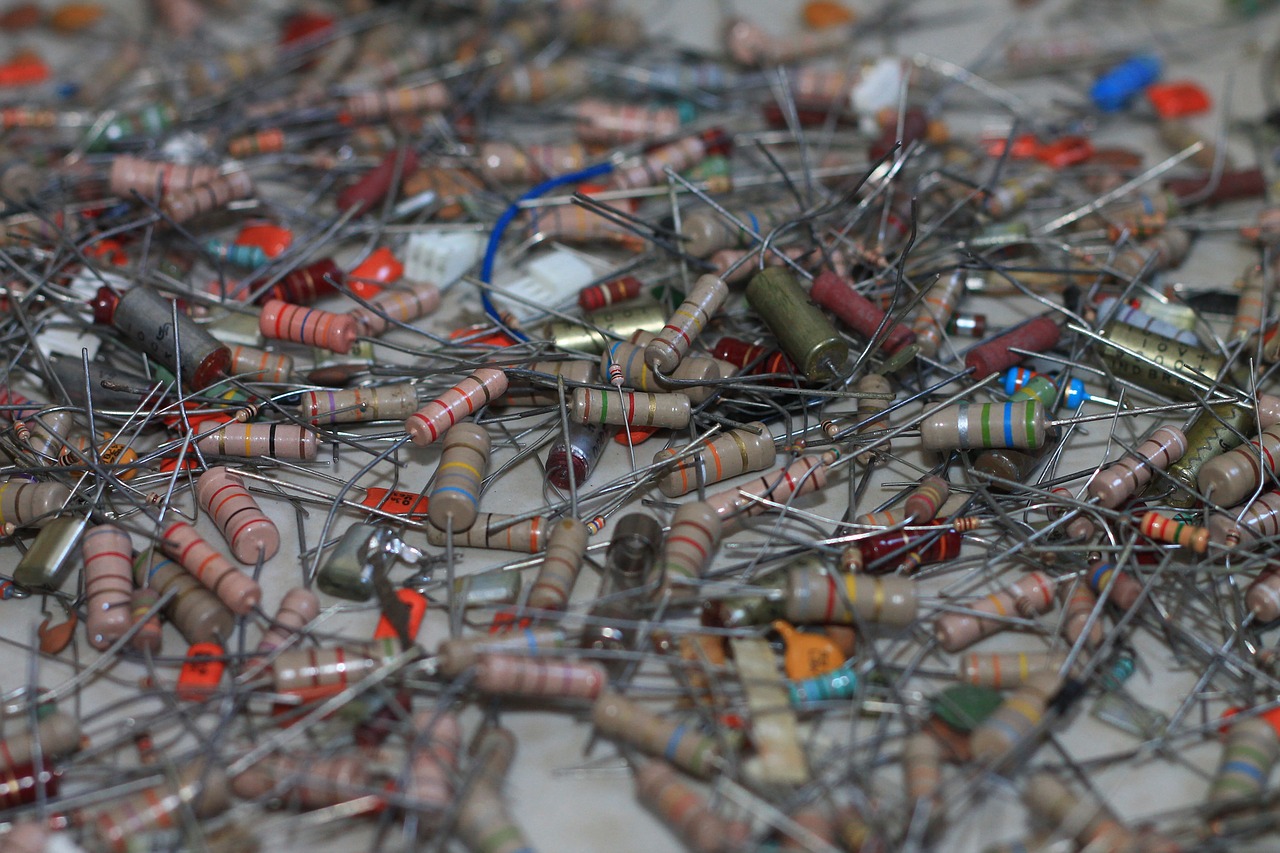
The colored bands indicate the resistance of any particular resistor.
If you know the resistance of individual resistors, you can calculate the equivalent
resistance of a system of resistors, arranged in series and in parallel.
Consider 2 identical resistors in series.
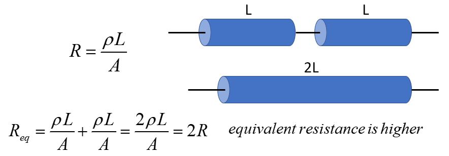
Assume we have zero resistance in the connecting wire.
Since resistance is proportional to length, the equivalent resistor has double the length of either resistor.
Adding them together just gives Req = 2R.
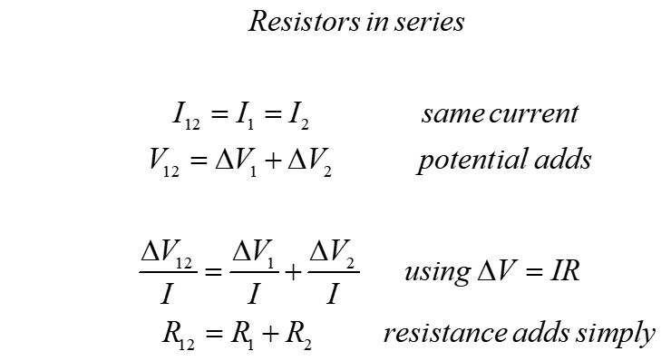
For any two resistors, we can use the facts that in series, the current through the resistors is the same current
and the potential drops over the resistors add to equal the total potentials drop.
In series, two resistors just add: Req = R1 + R2.
Now consider two identical resistors in parallel.
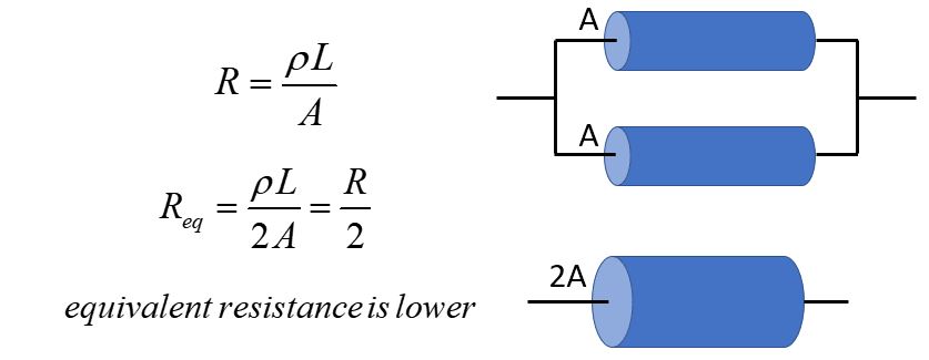
Now each resistor is connected separately to the battery.
The equivalent resistor has double the cross-sectional area of either resistor.
Resistance is inversely proportional to the cross-sectional area, so the equivalent resistor has half the resistance of
either individual resistor.
Adding them together gives Req = R/2.
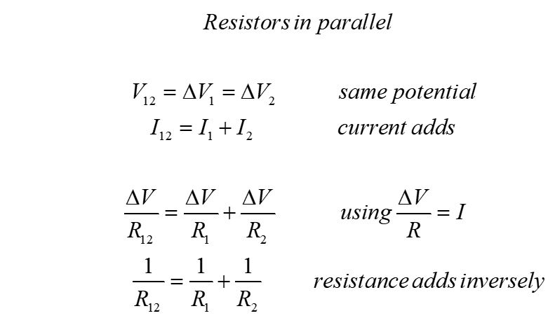
For any two resistors, we can use the facts that in parallel the potential drop across the resistors is the same
and the current adds, to find the equivalent resistance.
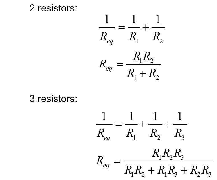
We use a little algebra to find a simple form for the equivalent resistance of two or more resisters in parallel.
Notice that the rules for adding resistors in series and in parallel are opposite the rules for adding capacitors.
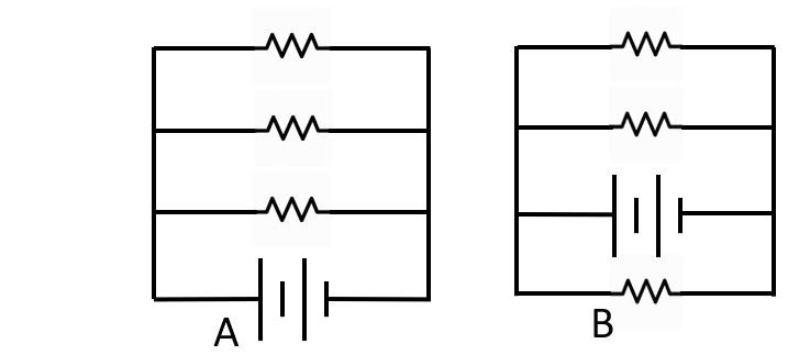
Resistors in parallel share a pathway to the battery.
These two parallel resistor circuits are fundamentally identical, assuming identical resistors.
It does not matter where the branch with the battery is placed, as long as the fundamental logic of the circuit is the same.
Measuring voltage and current
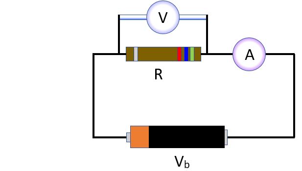
A voltmeter is an instrument for measuring the voltage difference between its two leads; an ammeter measures current between its two leads. Often, the two are combined into an instrument called a multimeter.
The voltmeter is connected with one lead on each side of a circuit component. In this diagram, it is measuring the voltage drop across a resistor in a circuit. A voltmeter has relatively high resistance, so as not to change the current in the circuit.
To measure current in a circuit, the circuit must be broken and the wires attached to both leads of the ammeter. The current of the circuit must go right throught the ammeter to be measured. An ammeter has relatively low resistance, so that it does not change the current in the circuit.
Voltage divider
A voltage divider is a simply a circuit with an input voltage and a system of parallel resistors. The circuit can be more complicated if the series
resistors are not just single resistors, but are configurations of resistors that can be treated as equivalent resistors.
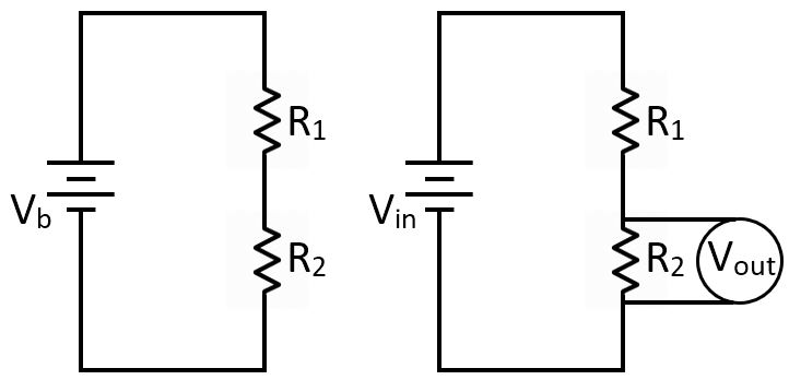
This is a simple voltage divider circuit. The "input voltage" is just the voltage of the battery and the "output voltage" is the voltage
measured across R2.

Voltage dividers are called "dividers" because they provide a simple way to calculate the output voltage as a fraction of the input voltage.
Here, we have derived the voltage divider equation for a simple circuit. It can be applied anywhere for resistors in series or equivalent resistors in series.
Sample questions
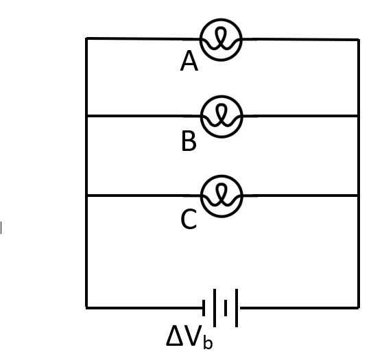
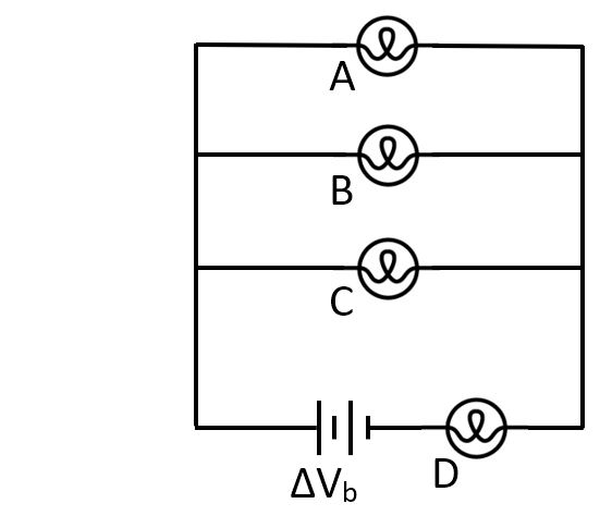
1. Which circuit is fundamentally different from the others?
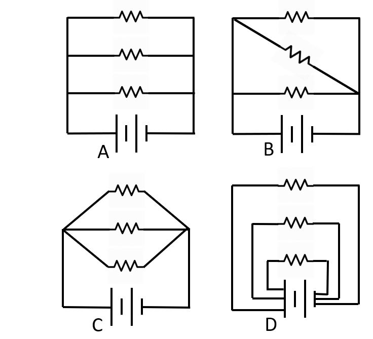
A. A
B. B
C. C
D. D
E. They are all the same
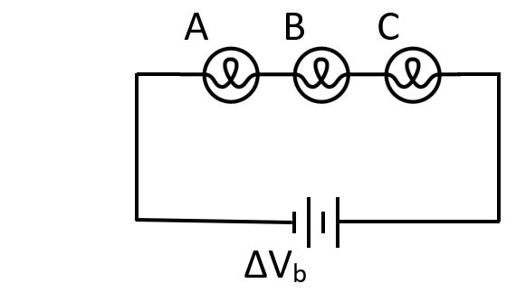
For the following questions, please consider identical light bulbs, and assume they can be treated as ohmic devices.
Assume the batteries are ideal batteries.
2. Three identical bulbs are in series. When you unscrew Bulb B, what happens to the other two?
3. Three identical bulbs are in parallel. When you unscrew Bulb B, what happens to the other two?
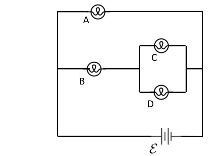
4. Rank the bulbs from brightest to dimmest.
A. C = D > B = A
B. A = B > C = D
C. A = B = C = D
D. A > B > C = D
E. A > C > B > D
5. Rank the bulbs from brightest to dimmest.
A. C = D > B > A
B. A > C = D > B
C. A = B = C = D
D. A > B > C = D
E. A > C > B > D
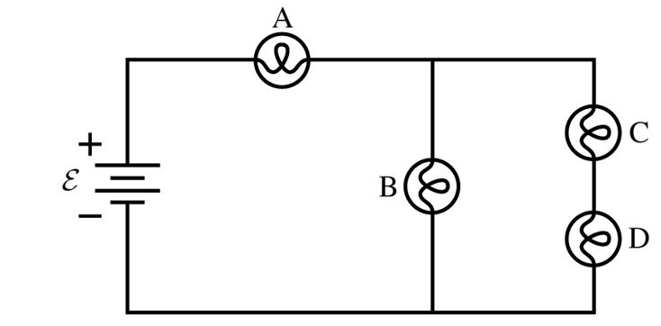
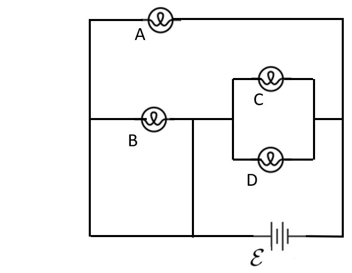
6. Consider this circuit with identical bulbs. When you unscrew Bulb B, what happens to Bulb D?
A. Bulb D gets brighter
B. Bulb D gets dimmer
C. Bulb D goes out
D. Bulb D stays the same
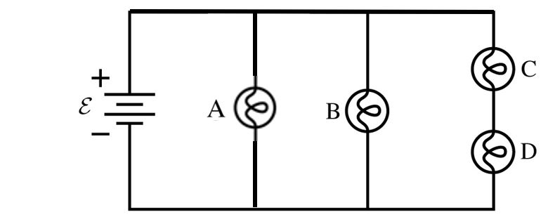
7. Rank the bulbs from brightest to dimmest.
A. A > B > C > D
B. A = B > C = D
C. A > B > C = D
D. B > A > C = D
E. A = C = D > B
8. Rank the bulbs from brightest to dimmest.
A. A > B > C > D
B. A = B > C = D
C. A > B > C = D
D. B > A > C = D
E. A = C = D > B
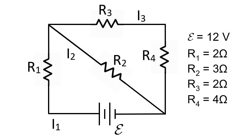
9. Find the currents in this circuit.