Inductors
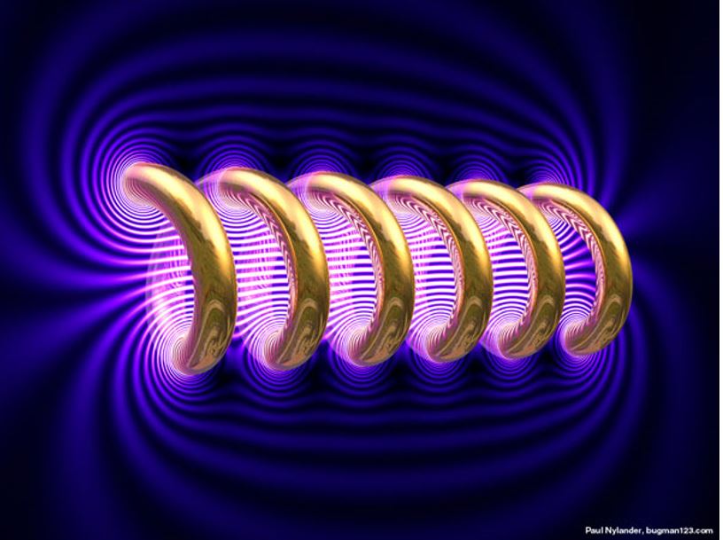
image source
A coil of wire can store potential energy in its magnetic field. It can be useful to include a coil as a component in an electric circuit. We call this kind of circuit component an "inductor" and symbolize it with a spiral.
Inductance L is defined as magnetic flux per current.
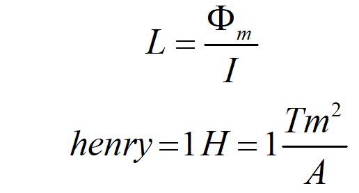
The unit of induction is the henry, and is defined as one tesla meter squared per ampere.
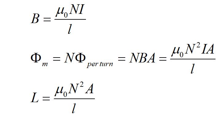
We use our definition of the magnetic field of a solenoid of N turns and cross-sectional area A and length l to find the inductance of an inductor with current I. Here, the magnetic flux is just BA.
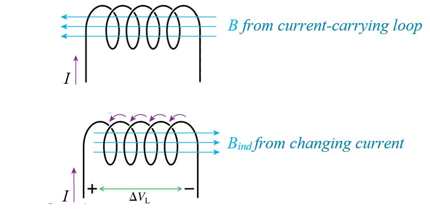
Current going through an inductor creates a magnetic field B. If the current is changing, an induced magnetic field opposes the change in magnetic flux. The induced current carries positive charges (to the left in the diagram). This charge separation creates a potential difference across the inductor.
In essence, the inductor acts like a battery in the circuit that opposes the change in current.
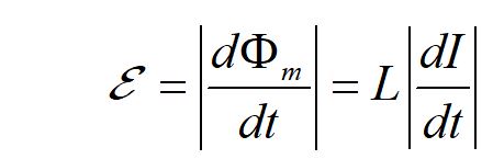
We can use Faraday's law to determine the induced EMF across an inductor interms of the changing magnetic flux or in terms of the inductance and the changing current.
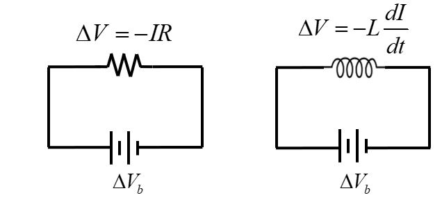
Recall that the voltage drops across a resistor when the path is in the same direction as the current. For an inductor, the potential decreases if the current is increasing, and the potential increases if the current is decreasing.
Energy stored in magnetic field
Recall that capacitors store energy between their plates as electrical potential energy. Inductors can store energy in the their magnetic fields.
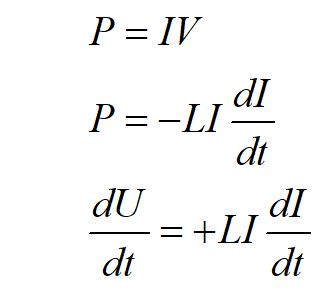
We can find the potential energy stored in the magnetic field of an inductor by considering the potential lost across an inductor. By conservation of energy, the magnetic potential energy stored by an inductor must be equal but opposite in sign to the electric potential energy lost by the inductor.
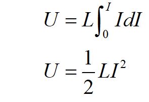
We evaluate the integral over the currrent I to find the energy stored in the magnetic field.
We can find the potential energy stored in the magnetic field of an inductor by considering the potential lost across an inductor. By conservation of energy, the magnetic potential energy stored by an inductor must be equal but opposite in sign to the electric potential energy lost by the inductor.
We evaluate the integral over the currrent I to find the energy stored in the magnetic field.
LC circuits
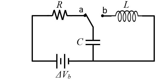
An LC circuit consists of at least one inductor and at least one capacitor.
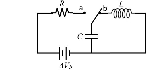
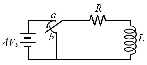
Consider the circuit diagrammed above.
After the switch has been closed to position "a" long enough to fully charge the capacitor, we close the switch to the "b" position.
The current starts to flow slowly from the positive plate because the inductor opposes the current, like an opposing battery.
The energy stored inthe inductor's B field decreases and the charge flows faster until the current reaches maximum.
At max current, the current stops changing and the inductor acts like a wire. If there was no inductor, the current would stop flowing.
But the inductor resists the change in current, so the current keeps flowing, and flows until the capacitor
it fully charged with the opposite polarity. Then the current flows again, only in reverse until the capacitor is
again fully charged in its original polarity.
The current oscillates back and forth through the circuit at a resonant frequency. If there is no resistance in the circuit, this resonant behavior continues indefinitely.
We can find the resonant frequency of an LC circuit by considering its governing differential equation. We start by using the voltage loop rule.
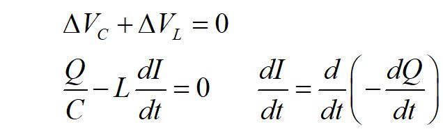
We substitute the terms for the potentials for the capacitor and inductor. Notice the sign for the change in current is negative, reflecting that the charge was removed from the capacitor. The charge flowing through the inductor results from a decrease of charge in the capacitor.

We rearrange the terms in our differential equation.
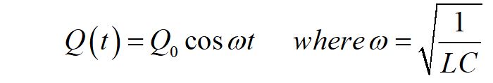
From the form of the differential equation, we know the solution will be oscillatory. The resonant frequency of the circuit is the inverse square root of the product of the capacitance and the inductance. Note that Q here is the charge on the capacitor.
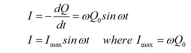
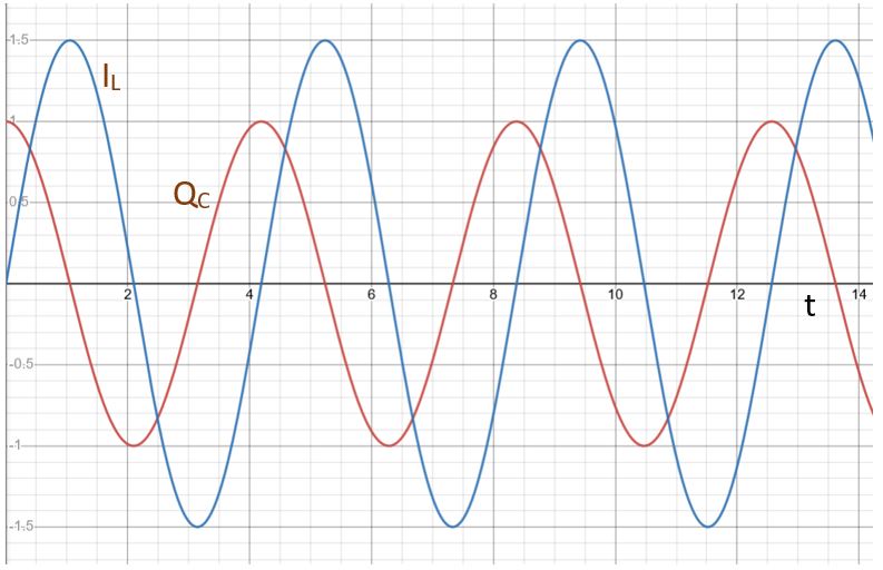
We can find an expression for the current in the circuit by taking the time derivative of the charge equation.
At max current, the sine function equals 1 or -1 and the cosine function equals zero.
There is zero charge on the capacitor when the current is at maximum in either direction.
Practice questions